长文,以游戏Trigger Rally为例谈WebGL地形渲染
作者:Jasmine Kent
在本系列中,我将介绍WebGL游戏《Trigger Rally》中使用的地形渲染技术。
一个难题
在电脑图像和游戏中高效沉浸大面积、精细的地图是一个难题。

terrain3(from gamasutra)
使用WebGL(网页图形库)却可以使这个难题变得容易。WebGL是浏览器的OpenGL(开放图形语言),允许用户使用GPU的性能,但有一些限制。更重要的是,在本地应用中用 JavaScript处理CPU端的数据更慢。把数据转移到GPU,比在本地应用中要求更多的安全性检查,以保证网络用户安全。然而,一旦数据到GPU,绘制就非常快了。

gpu-good-cpu-bad(from gamasutra)
最大化GPU工作和最小化CPU工作的好办法是,在启动时把静态数据(顶点、指数和纹理)载入到GPU,然后在运行时用尽量少的调用渲染它。
但仅靠静态数据是很难做出漂亮的地形的,因为镜头通常会很接近地面,而在屏幕上看,最近处和最远处的地面之间的精细度差异会很明显。
另外,在给定的GPU交互率下,能够绘制的三角形的数量是有限的。三角形数量的多少取决于应用或游戏运行的系统,但通常不可能在整个平面上大面积地、精细地渲染。
因为三角形数量有限,我们必须找出最佳的三角形分配方案。所以,在接近镜头时我们以低细节均匀分布,因为于玩家不可能欣赏到更远处的细节。
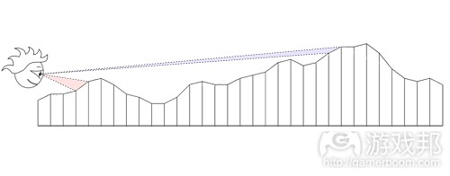
terrain-diagram1(from gamasutra)
注意,近处的视线(粉红部分)表面积比远处的视线(蓝色部分)的更大。理想情况下,我们会让接近镜头的地方比远离镜头的地方有更多三角形,以平均二者。
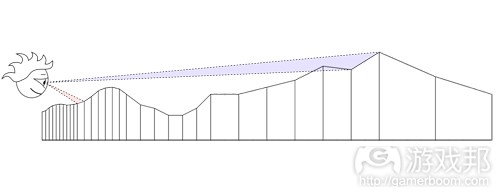
terrain-diagram2(from gamasutra)
但对于移动的视点和纯静态的顶点数据,这个方法并不太管用。
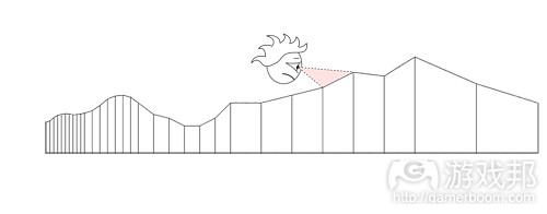
terrain-diagram3(from gamasutra)
如果你乐意做些CPU上的工作,那么你可以根据当前的视点,使用多种算法中的一种来调整地形的细节程度(LOD)。各个算法都以各自的方式平衡CPU的工作和GPU的工作。
解决方案:Geoclipmapping
我们如何用纯静态顶点数据达到可调节的LOD?Geoclipmapping和顶点纹理就是答案。
我们不是编码顶点数据中的高度信息,而是把它留在单独的纹理里。这样,我们的顶点数据可以用中央更高的分辨率和从源头开始的递减的分辨率环编码简单的网格模型。
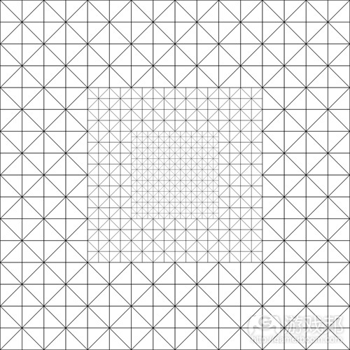
terrain-diagram4(from gamasutra)
在运行时,我们把这个网格模型放在当前视点之下,然后从顶点着色器的高地纹理地图中取样本。
事实上要做的事不止这些,所以在本系列的下一篇文章中,我将继续详细geoclipmapping的运作原理和执行方法。再之后,我将讨论多分辨率heightmapping和表面着色。
环形
Geoclipmap渲染使用一系列的方格“环绕”顶点,每个环都是此前环形的两倍,空间分辨率也是如此分布。这就形成了所有距离间的地形几乎一致的屏幕空间分辨率。位居最中央 (最高分辨率)的环拥有其中心填充,成为一个简单的三角方格:
以方格模式自我重复的几何形有一个良好的属性:我们不会让用户看到任何可视变化(除了移动的边缘),就可以通过准确的方格数量对其进行转换:
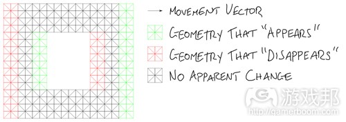
diagram5(from gamasutra)
我们可以运用这一属性移动几何体,令其接近摄像机之下,但不要让它的移动看起来过于明显。
每个环都有自己的方格大小,由于转换距离取决于几何大小,所以我们得分别移动这些环。因此就要让顶点着色器知道顶点属于哪个图层,这样才好让它正确变体。
所以我们需要的顶点属性就是:
*X轴位置
*Y轴位置
*图层属性
vertex attributes(from gamasutra)
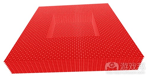
在《Trigger Rally》中,我们使用的是[X,Y,X]向量,并将图像索引编程为Z,这样我们的原几何图的环形就会堆叠起来。
填充空隙
每个环都用不同的比例绘制,它们还使用多个比例进行转变。这里就有一个问题:当一个环形转变了,而其旁边的环形却没有转变,那么这就会产生一个空隙。
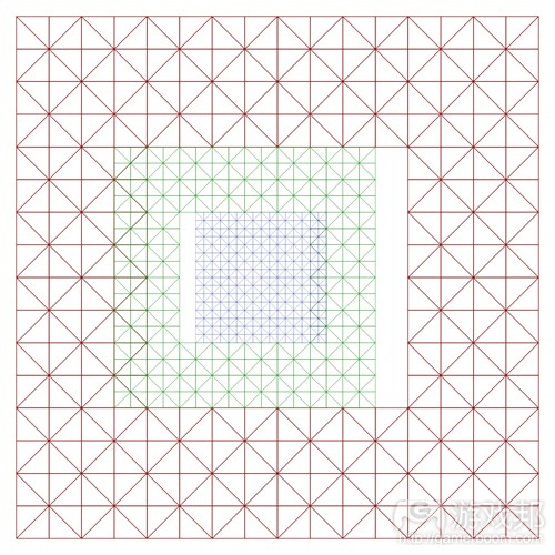
diagram8(from gamasutra)
修复这个空隙的一个方法就是使用额外几何形,即所谓的skirt扩大环形边缘。skirt是由许多更小的碎片集合而成,使用大量的小顶点缓冲器和谨慎的CPU逻辑,但这并非我们想要 的结果。
所在在部署《Trigger Rally》的地形时,我花了数个小时试图找到一种无缝而完全静态的skirt设计方法,但却无果而终。
之后我在去年的WebGL Camp Europe现场见到了Florian Bösch,他建议我将环形做得更大一点,然后让它们重叠。
现在,富有经验的图像程序员肯定会说“不行!你不能重叠几何图形!这太浪费了,并且你会看到糟糕的深度冲突问题!”不过除了有一点透支之外,这种方法还算是一种很棒的 解决方案,因为几何形匹配非常妥当。
变体
在这些环形的边缘之前,我们为几何形分配一个分辨率,令其紧挨着仅有其一半分辨率的几何形。我们必须在每个环形的边缘引进一个转换区域,仅几何形逐渐移动或从高分辨率 向低分辨率变体,这样当你到达环形边缘时,它就会与其相邻的环形完美匹配。
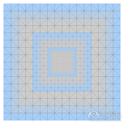
diagram6(from gamasutra)
以下就是每个顶点要与另一个环形相匹配时所需移动的方式:
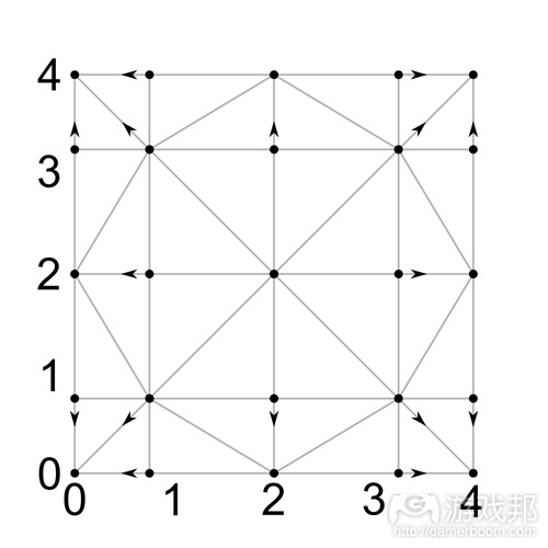
diagram7(from gamasutra)
我们要在顶点着色器中执行这种转换。最简单的方法莫过于将变体方向矢量作为顶点数据格式的一部分,但Florian对此却有更好的建议,即使用模运算!
让我们列出这些数据看看如何执行:
顶点坐标 0 1 2 3 4
MOD 2 0 1 0 1 0
MOD 4 0 1 2 3 0
变体矢量 0 -1 0 1 0
我们可以使用这个GLSL代码,从面点位置来计算变体矢量:
vec2 morphVector = mod(position.xy, 2.0) * (mod(position.xy, 4.0) – 2.0);
这不需要任何额外的顶点属性!
这次我们要看看地形高地数据是如何储存和处理的。
《Trigger Rally》的地形高地数据主要资源,形成山地的整体形状,是瑞士阿尔卑斯山地图的真实卫星数据。

terrain4(from gamasutra)
我写了一个工具把这个数据转化为无缝的1024×1024的16位图像。低8位储存在红色通道里,高8位存在绿色通道里。如下图所示:
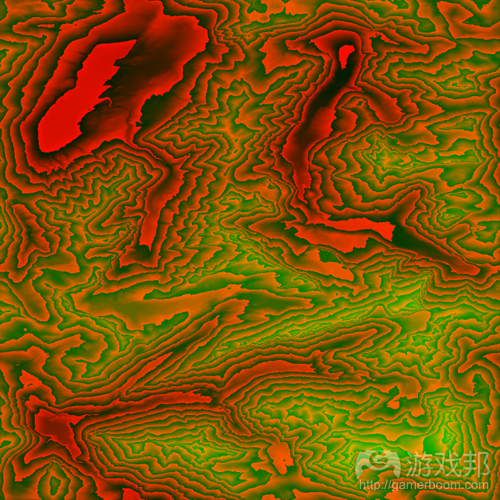
nice-boosted(from gamasutra)
在载入时,游戏把这个图像转化为单通道的32们浮动纹理,然后把赛车跑道曲线(每一条路道的曲线都是不一样的)绘制到这个图像中。
以角秒的速度取样高地数据,以21米对应阿尔卑斯山纬度30米。我把这些数值除以大约3,以缩小游戏中的高山,所以主高地地图的各个象素其实是7.5米x10.8米。
这样的分辨率对于高山是不错的,对于跑道只是刚好,而对于顺畅的驾驶和近景图像,就不太够了。
平滑
第一件要做的事就是修改高地地图。对于图像,线性过滤通常足够平滑了,但对于我们几何体,我们确实需要更高的连续性。这里有几个不同的办法,但我只采用三次厄密特条样 函数插值法。
我们得到的结果如下:
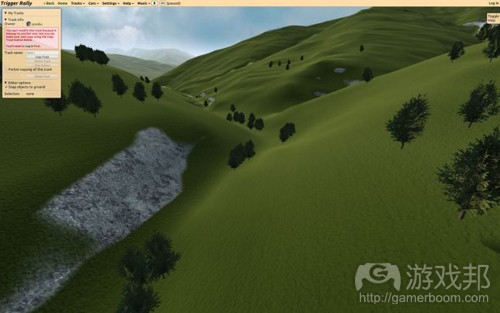
terrain7(from gamasutra)
添加细节
现在我们必须添加更高分辨率的细节,使地形更加有趣和真实。为此,我使用512×512的8位地图,其中高地储存在蓝色通道中,高地导数(游戏邦注:一个变量随某个变量变化时 的速度或变化率)存在红色和绿色通道中。
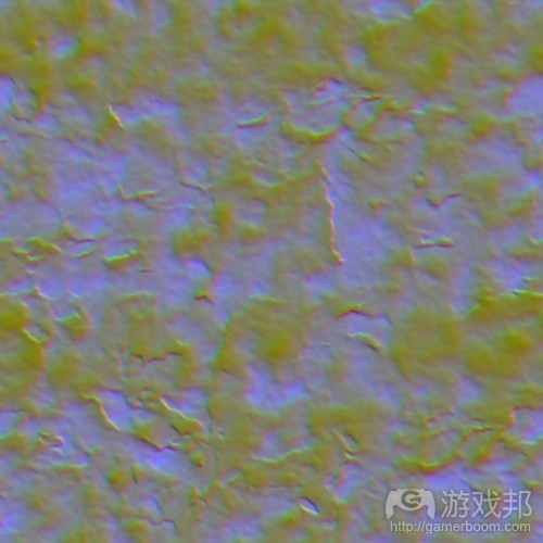
detail(from gamasutra)
以每个顶点1象素,最高的地形分辨率,取样这个细节地图,然后添加到主要高地上,使地图更加生动。
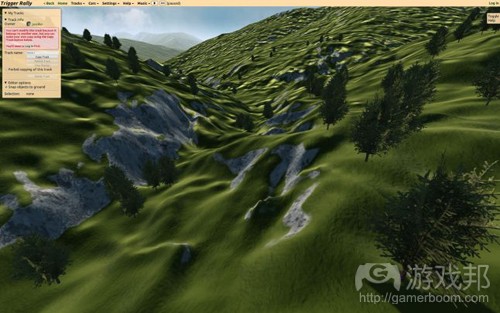
terrain8(from gamasutra)
调整细节地图上的地形渐变和接近跑道曲线的地方,使陡峭的区域更加崎岖,使山谷更加平整。这么做也使跑道更加漂亮和平整,尽管这是在编辑器中可配置的跑道曲线片段。
表面地图
着色器需要更多关于地图的信息,我把它存在“表面”地图中:
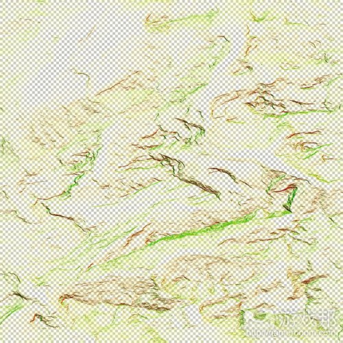
surface(from gamasutra)
R: d(高度)/dx
G: d(高度)/dy
B: 表面类型 (尘土或草地/石块)
A: 细节倍增器 (由渐变和路道邻近决定的)
相关拓展阅读:篇目1,篇目2,篇目3(本文由游戏邦编译,转载请注明来源,或咨询微信zhengjintiao)
WebGL Terrain Rendering in Trigger Rally – Part 1
by Jasmine Kent
In this series of posts, I’ll talk about the terrain rendering techniques used in the WebGL game Trigger Rally.
An Interesting Problem
Rendering large, detailed terrains efficiently is an interesting problem in computer graphics and games.
Note: JavaScript performance is an area of intense interest to HTML5 game developers. This article covers some recent developments and asm.js in particular.
Doing it with WebGL makes it even more interesting. WebGL is OpenGL for the browser, providing access to the power of the GPU, but with some constraints. Importantly, CPU-side data processing with JavaScript is slower than in a native app. Transferring data to the GPU involves more security checks than in a native app, to keep Web users safe. However, once the data is on the GPU, drawing with it is fast.
A great way to maximize GPU work and minimize CPU work is to load static data (vertices, indices and textures) onto the GPU at start-up, and render it at runtime with as few draw calls as possible.
But it’s hard to make terrain look good with purely static data. Because the viewpoint will often be close to the ground surface, there can be many orders of magnitude difference in screen-space resolution between the closest and furthest parts of the terrain.
Furthermore, there are limits to the number of triangles that a given GPU can draw at interactive rates. Your triangle budget will depend on what range of systems you would like your app or game to be enjoyed on, but generally you can not afford to render a large terrain at full detail across its entire surface.Since triangle budget is limited, we have to decide how we should distribute triangles for best effect. A uniform distribution results in low detail close to the camera, and excessive detail that the user can’t appreciate further away:
Notice that the red segment has a much larger apparent (on-screen) size than the blue segment. Ideally we would like to even this out by using more triangles close to the camera, and fewer at a distance:
But this doesn’t work so well with a moving viewpoint and purely static vertex data:
If you’re willing to do some work on the CPU, you can use one of many algorithms to adapt the level of detail (LOD) of terrain to the current viewpoint. Each algorithm balances the work between CPU and GPU in its own way.
Solution: Geoclipmapping
How can we achieve adaptive LOD with purely static vertex data? Geoclipmapping and vertex texturing to the rescue!
Instead of encoding height information in the vertex data, we keep it in a separate texture. Our vertex data can then encode a simple mesh with a higher resolution in the center, and rings of decreasing resolution as you move away from the origin:
At runtime, we position this mesh underneath the current viewpoint, and take samples from a height texture map in the vertex shader.
There’s actually a bit more to it than this, so in the next article I’ll go into the specifics of how it works, and how to implement geoclipmapping with morphing efficiently in WebGL. After that, I’ll discuss multiresolution heightmapping and surface shading.
The following blog post, unless otherwise noted, was written by a member of Gamasutra’s community.
The thoughts and opinions expressed are those of the writer and not Gamasutra or its parent company.
Welcome to this series of posts about WebGL Terrain Rendering in Trigger Rally!
If you haven’t yet, you should read Part 1 where I talk about the importance of minimizing CPU-GPU data transfer, and introduce the idea of combining static vertex buffers with height data stored in textures.
In this post, I’ll discuss the vertex data format and morphing.
Rings
Geoclipmap rendering uses a set of square “rings” around the viewpoint, where each ring is twice the size of the previous one, and so has half the spatial resolution. This results in approximately consistent screen space resolution of the terrain at all distances. The innermost (highest resolution) ring has its center filled in, becoming a simple square grid of triangles:
Geoclipmapping rings
Geometry that repeats itself in a grid pattern has a nice property: we can translate it by exact multiples of the grid size without any visible change to the user, except that the edges appear to have moved:
Translating a ring
We can use this property to move the geometry around, keeping it approximately centered under the camera, but without it being obvious that this movement is occurring.
Each ring has its own grid size, and since the translation distance depends on the geometry size, we will need to move the rings independently of each other. Thus the vertex shader needs to know which layer a vertex belongs to, both for translation and so that it can morph it correctly (we’ll come back to morphing in a minute.)
Raw vertex dataSo the vertex attributes we need are:
Position X
Position Y
Layer index
In Trigger Rally’s implementation, we use an [X,Y,Z] 3-vector and encode the layer index as Z, so that in our raw geometry the rings appear to be stacked.
Filling in the gaps
Each ring is drawn at a different scale, and they are also translated by multiples of this scale. So there is a problem: when one ring is translated but its neighbor is not, a gap will appear:
Gaps when rings are translated
One way of fixing this is to extend the edge of the ring with extra geometry, known as a skirt. In the geoclipmapping approached described in this paper, the skirt is carefully assembled from many smaller pieces, using multiple small vertex buffers and careful CPU logic. We don’t want that!
When implementing the terrain in Trigger Rally, I spent hours trying to find a clever way to design the skirt to be both seamless and entirely static, to no avail.
But then I met Florian Bösch at last year’s WebGL Camp Europe, and he suggested just making the rings bigger and letting them overlap.
Now, seasoned graphics programmers will probably be gasping “No! You can’t overlap geometry! It’s wasteful and you’ll get horrible depth fighting artifacts!” But other than a tiny bit of overdraw, it actually turns out to be an excellent solution provided that the geometry matches up exactly. Which brings us to…
Morphing
At the boundary between rings we have geometry at one resolution next to geometry at half that resolution. We need to introduce transition regions at the edge of each ring, where the geometry gradually moves or “morphs” from high resolution to low, so that by the time you reach the edge of the ring it will match up perfectly with the next ring beyond.
Geoclipmapping ring transition regions
Here’s how each vertex needs to move in order to match the next ring:
Vertex movement diagram
We need to perform this translation in the vertex shader. The simplest approach would be to include the morph direction vector as part of the vertex data format, but again Florian had a better suggestion: use modular arithmetic!
To show how this works, let’s tabulate the data:
Vertex coordinate 0 1 2 3 4
MOD 2 0 1 0 1 0
MOD 4 0 1 2 3 0
Morph vector 0 -1 0 1 0
So we can compute the morph vector from the vertex position with this GLSL code:
vec2 morphVector = mod(position.xy, 2.0) * (mod(position.xy, 4.0) – 2.0);
No extra vertex attributes needed!
Tune in next time
In the next post, I’ll talk about how multi-resolution height data is stored in Trigger Rally, and how it’s processed in the vertex shader. After that we’ ll look at surface shading in the fragment shader, and how to render scenery meshes efficiently.
This time we’ll look at how the terrain height data is stored and processed!
Trigger Rally’s primary source of terrain height data, forming the overall shape of the mountains, is real satellite data from the Engelberg region of the Swiss Alps. A big thank you to Jonathan de Ferranti of viewfinderpanoramas.org for permission to use his Digital Elevation Map collection!
I wrote a tool to convert the data into a tileable 1024×1024 16 bit image. The low 8 bits are stored in the red channel and the high 8 bits in the green. Here it is, with the green channel amplified for illustration:
At load time, the game transforms this into a single channel 32 bit float texture. It then draws the racing track spline (which is different for each track) onto this image.
The height data is sampled in arc seconds, which corresponds to about 21m by 30m at Alpine latitudes. I’ve scaled down the mountains in the game by a factor of about 3, so each pixel of the primary height map is 7.5m by 10.8m.
This resolution is fine for the mountains and just about enough for the track, but it’s not enough to be smooth to drive on, nor is it visually interesting in the foreground.
Keeping it smooth
The first thing to do is smoothly interpolate the height map. Linear filtering is usually smooth enough for images, but for geometry we really need higher order continuity. There are various options here, but I went with Catmull-Rom interpolation.
So far we have something like this:
Adding more detail
Now we need to add some higher-resolution detail to make the terrain more interesting and plausible. For this I use a 512×512 8 bit map with height in the blue channel, and height derivatives in red and green:
Sampling this detail map at 1 pixel per vertex at the highest terrain resolution and adding it to the primary height makes things look a whole lot better:
The detail map is modulated by the terrain gradient and by proximity to the track spline. This makes steep areas bumpier, and valleys smoother. It also keeps the track (where you have to drive!) nice and smooth, although this is configurable per track spline segment in the editor.
Surface map
The shaders need some extra information about the terrain, which I store in a “surface” map:
R: d(height)/dx
G: d(height)/dy
B: surface type (dirt or grass/rock)
A: detail multiplier (determined by gradient and track proximity)





 闽公网安备35020302001549号