分享《Trigger Rally》的WebGL地形渲染技巧(2)
作者:Jasmine Kent
我们曾在第1部分中提到最小化CPU-GPU数据传送的重要性,并介绍了整合静态顶点缓冲器与纹理中存储的海拔数据这一理念。(请点击此处阅读本文第3部分)
我将在本文讨论顶点数据格式和变体的问题。
环形
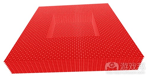
Geoclipmap渲染使用一系列的方格“环绕”顶点,每个环都是此前环形的两倍,空间分辨率也是如此分布。这就形成了所有距离间的地形几乎一致的屏幕空间分辨率。位居最中央(最高分辨率)的环拥有其中心填充,成为一个简单的三角方格:
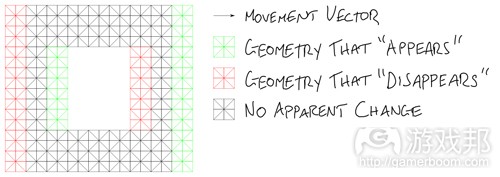
以方格模式自我重复的几何形有一个良好的属性:我们不会让用户看到任何可视变化(除了移动的边缘),就可以通过准确的方格数量对其进行转换:
我们可以运用这一属性移动几何体,令其接近摄像机之下,但不要让它的移动看起来过于明显。
每个环都有自己的方格大小,由于转换距离取决于几何大小,所以我们得分别移动这些环。因此就要让顶点着色器知道顶点属于哪个图层,这样才好让它正确变体。
所以我们需要的顶点属性就是:
*X轴位置
*Y轴位置
*图层属性
在《Trigger Rally》中,我们使用的是[X,Y,X]向量,并将图像索引编程为Z,这样我们的原几何图的环形就会堆叠起来。
填充空隙
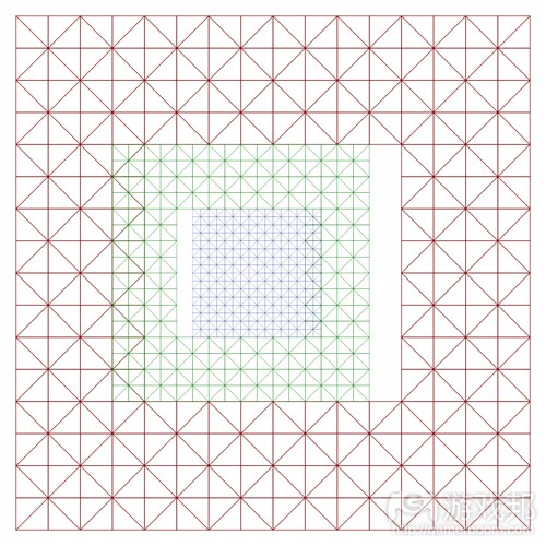
每个环都用不同的比例绘制,它们还使用多个比例进行转变。这里就有一个问题:当一个环形转变了,而其旁边的环形却没有转变,那么这就会产生一个空隙。
修复这个空隙的一个方法就是使用额外几何形,即所谓的skirt扩大环形边缘。skirt是由许多更小的碎片集合而成,使用大量的小顶点缓冲器和谨慎的CPU逻辑,但这并非我们想要的结果。
所在在部署《Trigger Rally》的地形时,我花了数个小时试图找到一种无缝而完全静态的skirt设计方法,但却无果而终。
之后我在去年的WebGL Camp Europe现场见到了Florian Bösch,他建议我将环形做得更大一点,然后让它们重叠。
现在,富有经验的图像程序员肯定会说“不行!你不能重叠几何图形!这太浪费了,并且你会看到糟糕的深度冲突问题!”不过除了有一点透支之外,这种方法还算是一种很棒的解决方案,因为几何形匹配非常妥当。
变体
在这些环形的边缘之前,我们为几何形分配一个分辨率,令其紧挨着仅有其一半分辨率的几何形。我们必须在每个环形的边缘引进一个转换区域,仅几何形逐渐移动或从高分辨率向低分辨率变体,这样当你到达环形边缘时,它就会与其相邻的环形完美匹配。
以下就是每个顶点要与另一个环形相匹配时所需移动的方式:
我们要在顶点着色器中执行这种转换。最简单的方法莫过于将变体方向矢量作为顶点数据格式的一部分,但Florian对此却有更好的建议,即使用模运算!
让我们列出这些数据看看如何执行:
顶点坐标 0 1 2 3 4
MOD 2 0 1 0 1 0
MOD 4 0 1 2 3 0
变体矢量 0 -1 0 1 0
我们可以使用这个GLSL代码,从面点位置来计算变体矢量:
vec2 morphVector = mod(position.xy, 2.0) * (mod(position.xy, 4.0) – 2.0);
这不需要任何额外的顶点属性!
总结
我将在下部分文章中讨论《Trigger Rally》如何存储多分辨率海拔数据,以及它如何在顶点着色器中处理。之后我们还将探讨碎片着色器中的表面着色,以及如何高效地渲染布景网眼。(本文为游戏邦/gamerboom.com编译,拒绝任何不保留版权的转载,如需转载请联系:游戏邦)
WebGL Terrain Rendering in Trigger Rally – Part 2
by Jasmine Kent
The following blog post, unless otherwise noted, was written by a member of Gamasutra’s community.
The thoughts and opinions expressed are those of the writer and not Gamasutra or its parent company.
Welcome to this series of posts about WebGL Terrain Rendering in Trigger Rally!
If you haven’t yet, you should read Part 1 where I talk about the importance of minimizing CPU-GPU data transfer, and introduce the idea of combining static vertex buffers with height data stored in textures.
In this post, I’ll discuss the vertex data format and morphing.
Rings
Geoclipmap rendering uses a set of square “rings” around the viewpoint, where each ring is twice the size of the previous one, and so has half the spatial resolution. This results in approximately consistent screen space resolution of the terrain at all distances. The innermost (highest resolution) ring has its center filled in, becoming a simple square grid of triangles:
Geoclipmapping rings
Geometry that repeats itself in a grid pattern has a nice property: we can translate it by exact multiples of the grid size without any visible change to the user, except that the edges appear to have moved:
Translating a ring
We can use this property to move the geometry around, keeping it approximately centered under the camera, but without it being obvious that this movement is occurring.
Each ring has its own grid size, and since the translation distance depends on the geometry size, we will need to move the rings independently of each other. Thus the vertex shader needs to know which layer a vertex belongs to, both for translation and so that it can morph it correctly (we’ll come back to morphing in a minute.)
Raw vertex dataSo the vertex attributes we need are:
Position X
Position Y
Layer index
In Trigger Rally’s implementation, we use an [X,Y,Z] 3-vector and encode the layer index as Z, so that in our raw geometry the rings appear to be stacked.
Filling in the gaps
Each ring is drawn at a different scale, and they are also translated by multiples of this scale. So there is a problem: when one ring is translated but its neighbor is not, a gap will appear:
Gaps when rings are translated
One way of fixing this is to extend the edge of the ring with extra geometry, known as a skirt. In the geoclipmapping approached described in this paper, the skirt is carefully assembled from many smaller pieces, using multiple small vertex buffers and careful CPU logic. We don’t want that!
When implementing the terrain in Trigger Rally, I spent hours trying to find a clever way to design the skirt to be both seamless and entirely static, to no avail.
But then I met Florian Bösch at last year’s WebGL Camp Europe, and he suggested just making the rings bigger and letting them overlap.
Now, seasoned graphics programmers will probably be gasping “No! You can’t overlap geometry! It’s wasteful and you’ll get horrible depth fighting artifacts!” But other than a tiny bit of overdraw, it actually turns out to be an excellent solution provided that the geometry matches up exactly. Which brings us to…
Morphing
At the boundary between rings we have geometry at one resolution next to geometry at half that resolution. We need to introduce transition regions at the edge of each ring, where the geometry gradually moves or “morphs” from high resolution to low, so that by the time you reach the edge of the ring it will match up perfectly with the next ring beyond.
Geoclipmapping ring transition regions
Here’s how each vertex needs to move in order to match the next ring:
Vertex movement diagram
We need to perform this translation in the vertex shader. The simplest approach would be to include the morph direction vector as part of the vertex data format, but again Florian had a better suggestion: use modular arithmetic!
To show how this works, let’s tabulate the data:
Vertex coordinate 0 1 2 3 4
MOD 2 0 1 0 1 0
MOD 4 0 1 2 3 0
Morph vector 0 -1 0 1 0
So we can compute the morph vector from the vertex position with this GLSL code:
vec2 morphVector = mod(position.xy, 2.0) * (mod(position.xy, 4.0) – 2.0);
No extra vertex attributes needed!
Tune in next time
In the next post, I’ll talk about how multi-resolution height data is stored in Trigger Rally, and how it’s processed in the vertex shader. After that we’ll look at surface shading in the fragment shader, and how to render scenery meshes efficiently.(source:gamasutra)


 闽公网安备35020302001549号