分享数字建模方法——从平面到盒子(1)
作者:Jayelinda Suridge
什么是程序几何体?
程序几何体就是用代码建模的几何体。通常情况下,制作3D mesh(3D网格模型)是手动操作美术软件如Maya、3DS Max或者Blender等完成的,而本文要介绍的做法却是使用程序指令构建mesh。(请点击此处阅读本文第2部分)
这可以在运行时间(mesh直到终端用户运行程序时才完成)、编辑时间(当应用正在开发时,使用脚本或工具)或在3D美术包(使用脚本语言如MEL或MaxScript)里完成。
程序生成mesh的优点在于:
多样性:可以用随机变量生成mesh,也就是说,你可以避免重复制作几何体。
可扩展性:mesh的细节程度可以由终端用户的机器性能或偏好来决定。
可控制性:不了解3D建模软件的游戏/关卡设计师可以理好地控制关卡的外观。
速度:一个对象可以简单迅速地生成多个变体。
谁说的?
以下是本人的背景:我是一名3D美工转游戏程序员再转独立开发者,我认为思考如何用脚本制作出一样东西是非常有趣的。当然,这种乐趣不是谁都能体会,不过没关系。
以下是我自己的游戏项目中的案例:
(《Stranger’s Call》的由程序生成的关卡:左半边是最高细节设置,右半边是最低细节设置,因为这些是根据随机生成的布局产生的,所以不可能出现相同的关卡)。
(《Ludus silva》中的植物——这些是玩家在游戏中制作/编辑的)。
曾经有人看到这些图像后问我怎么做出来的。好吧,是用一些基本的形状再添加一些细节做成的。我做过的大部分程序生成的东西都是由两种基本形状构成的:平面和圆柱体。
接下来我们就来学习如何制作吧。
预备知识
本文中出现的所有案例都是使用C#和Unity制作的。所有重要的概念都可以转化为你自己习惯的语言/引擎。
你必须掌握C#的基础,如果还懂一些3D几何体的知识就更好了。
不确定自己的知识储备是否足够的人可以做下面的测试:
1、什么是class、function、array,以及loop?
2、如果我用C#语言写出来,你会不会认得出?
3、你了解3D向量是什么吗?(Unity中的Vector3结构)
4、你知道如何获得从一个点到另一点的方向吗?
怎么样?全部会吗?那就太好了。
不太会?那你可能得去学习一下《官方Unity脚本教程》和“基础C#教程”。
什么是mesh?
大部分学过3D美术或至少了解过3D美术的人都可以跳过这部分。对于那些完全不懂3D美术的人,可以学习一下这些简要的介绍。
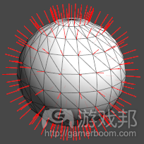
我们后面要构建的是一个polygon mesh(多边形网格模型)。可以把它当成3D空间中的一系列顶点(vertices)构成的一系列三角形,每个三角形三个顶点之间形成平面。三角形可以也可以不共享顶点。
(两个3D mesh。左边是灯光渲染后的模型,右边是三角形线条结构。)
三角形和多边形
在我们继续学习以前,首先要理清一些常用的术语。你可能听说过“poly-count”或“high-poly”/“low-poly”之类的术语。这其中的“多poly”通常是指三角形,但最好还能了解一下谁使用这些术语。大多数3D建模软件允许美工用任意边的多边形制作模型。这种软件生成的poly-count通常计算的是那些图形。但当需要渲染时,那些形状通常得分成三角形,因为那样形像软件才能理解。Unity的Mesh class也只能理解三角形。所以我们也将使用三角形建模。
除了三角形和3D位置,我们还要给mesh添加其他数据,如法线(normal)。所谓的“法线”就是与顶点垂直的向外方向。在光照mesh时要用到法线。
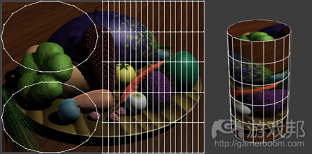
另一个要添加的另一个东西是UV座标(或简称为UV)。当给网格模型添加材质时就会用到UV。UV座标是2D空间的位置。在那个座标上的材质的像素会被贴到mesh的对应位置上。UV通常是打开的,因为这样可以把它们理解为从mesh上剥离下来的表面,然后摊平放在材质空间中。
以上就是mesh的基本知识。下面我们来做几个mesh。
内容
本教程有些长度,所以我分成了如下几个部分:
1-1、平面:从平面到盒子
1-2、平面的进一步运用:制作两个物品—-房子和围栏
2-1、圆柱体:基本物品—-蘑菇和花
1-1:平面
Unity材料:Unity程序包中包含本教程使用到的脚本和场景。
资源文件夹:就是资源文件。
好吧,我们从quad(四方形)开始吧。
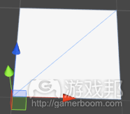
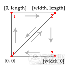
最简单的形状。这是一个基本平面,有4个顶点,和两个三角形。
我们从我们必需的组件开始制作。这个mesh有顶点、三角形、法线和UV座标。绝对必要的部分只有顶点和三角形。如果你的模型不需要在场景中光照,那么就不需要法线。如果你的模型不需要贴材质,那么就不需要UV。
Vector3[] vertices = new Vector3[4];
Vector3[] normals = new Vector3[4];
Vector2[] uv = new Vector2[4];
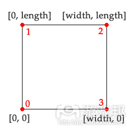
现在我们给顶点赋一些值。以上代码有两个之前定义好的变量:m_Width和m_Length。你应该知道表示的是quad的宽度和长度吧。
这个mesh是在XZ面创建的,所以法线的方向与Y轴一致(适合做地面)。你也可以按自己的习惯改用XY面,用Z轴做法线(适合做看板)。
位置值从0.0f开始到长度/宽度,也就是用[0.0, 0.0] 作为mesh的一个顶点位置。mesh的源点就是它的轴点,所以这个mesh就会以那个顶点为旋转点。如果你愿意,还可以通过偏移宽度和长度来使那个值减半,这样轴点位于中央。
vertices[0] = new Vector3(0.0f, 0.0f, 0.0f);
uv[0] = new Vector2(0.0f, 0.0f);
normals[0] = Vector3.up;vertices[1] = new Vector3(0.0f, 0.0f, m_Length);
uv[1] = new Vector2(0.0f, 1.0f);
normals[1] = Vector3.up;vertices[2] = new Vector3(m_Width, 0.0f, m_Length);
uv[2] = new Vector2(1.0f, 1.0f);
normals[2] = Vector3.up;vertices[3] = new Vector3(m_Width, 0.0f, 0.0f);
uv[3] = new Vector2(1.0f, 0.0f);
normals[3] = Vector3.up;
现在我们来做三角形。三角形是由3个整数确定的,各个整数就是角的顶点的index。各个三角形的顶点的顺序通常由下往上数的,可以是顺时的也可以是逆时的,这取决于我们从哪个方向看三角形。通常,当mesh渲染时,逆时针的面会被挡掉。我们希望保证顺时针的面与法线的主向一致(即向上)。
int[] indices = new int[6]; //2 triangles, 3 indices each
indices[0] = 0;
indices[1] = 1;
indices[2] = 2;indices[3] = 0;
indices[4] = 2;
indices[5] = 3;
现在我们整理一下。在Unity中,这只是给我们刚才做的所有array赋给一个Unity Mesh class的实例。我们在最后调用RecalculateBounds()来重新计算mesh的大小(渲染需要)。
Mesh mesh = new Mesh();
mesh.vertices = vertices;
mesh.normals = normals;
mesh.uv = uv;
mesh.triangles = indices;mesh.RecalculateBounds();
现在我们做好一个mesh了。在Unity场景中,我们把这个脚本添加到包含mesh过滤器和渲染器组件的GameObject中。以下代码寻找mesh过滤器并把刚做好的模型赋给它。这个模型现在作为一个物品的一个部分存在于场景中。
MeshFilter filter = GetComponent();
if (filter != null)
{
filter.sharedMesh = mesh;
}
You have now made your first procedural mesh.
这样你就做好了你的第一个程序生成mesh。
做计划
好吧,我们现在假设要做一个程序生成的物品。最无聊的部分就是一次又一次地写相同的mesh初始代码,但还不至于像因为出现错误而被迫重写那么让人郁闷。
using UnityEngine;
using System.Collections;
using System.Collections.Generic;public class MeshBuilder
{
private List m_Vertices = new List();
public List Vertices { get { return m_Vertices; } }private List m_Normals = new List();
public List Normals { get { return m_Normals; } }private List m_UVs = new List();
public List UVs { get { return m_UVs; } }private List m_Indices = new List();
public void AddTriangle(int index0, int index1, int index2)
{
m_Indices.Add(index0);
m_Indices.Add(index1);
m_Indices.Add(index2);
}public Mesh CreateMesh()
{
Mesh mesh = new Mesh();mesh.vertices = m_Vertices.ToArray();
mesh.triangles = m_Indices.ToArray();//Normals are optional. Only use them if we have the correct amount:
if (m_Normals.Count == m_Vertices.Count)
mesh.normals = m_Normals.ToArray();//UVs are optional. Only use them if we have the correct amount:
if (m_UVs.Count == m_Vertices.Count)
mesh.uv = m_UVs.ToArray();mesh.RecalculateBounds();
return mesh;
}
}
你需要的所有数据都在一个class中,它很容易在两个函数之间通过。另外,因为我们使用的是列表,而不是array,所以不会误算顶点或三角形的数量。这样还更容易组合mesh:只要用相同的MeshBuilder生成就行了。
注:这是我在自己的项目中使用的class的简化版。本版不能做的事,包括切线和顶点颜色,或为大mesh保留的空间,或者变更这个Mesh class中已存在的实例。
现在,使用这个class,我们的quad生成代码如下:
MeshBuilder meshBuilder = new MeshBuilder();
//Set up the vertices and triangles:
meshBuilder.Vertices.Add(new Vector3(0.0f, 0.0f, 0.0f));
meshBuilder.UVs.Add(new Vector2(0.0f, 0.0f));
meshBuilder.Normals.Add(Vector3.up);meshBuilder.Vertices.Add(new Vector3(0.0f, 0.0f, m_Length));
meshBuilder.UVs.Add(new Vector2(0.0f, 1.0f));
meshBuilder.Normals.Add(Vector3.up);meshBuilder.Vertices.Add(new Vector3(m_Width, 0.0f, m_Length));
meshBuilder.UVs.Add(new Vector2(1.0f, 1.0f));
meshBuilder.Normals.Add(Vector3.up);meshBuilder.Vertices.Add(new Vector3(m_Width, 0.0f, 0.0f));
meshBuilder.UVs.Add(new Vector2(1.0f, 0.0f));
meshBuilder.Normals.Add(Vector3.up);meshBuilder.AddTriangle(0, 1, 2);
meshBuilder.AddTriangle(0, 2, 3);//Create the mesh:
MeshFilter filter = GetComponent();if (filter != null)
{
filter.sharedMesh = meshBuilder.CreateMesh();
}
开始做几何体
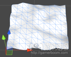
你的关卡地形,其实是一个平坦的平面。
注:这里的“不平坦”是由于给各个顶点赋了随机高度。这么做是因为可以让代码漂亮简单,不是因为可以让地形好看。如果你是很认真地要做一个地形mesh,你最好使用heightmap或perlin noise等算法。
这个地形可以当作是一系列排列在网格中的quad。这正是我们要做的第一步。首先,我们定度一个生成我们刚才做的quad的函数。只有这个函数会把参数作为位置offset(平移)值,这是添加到顶点位置的。
void BuildQuad(MeshBuilder meshBuilder, Vector3 offset)
{
meshBuilder.Vertices.Add(new Vector3(0.0f, 0.0f, 0.0f) + offset);
meshBuilder.UVs.Add(new Vector2(0.0f, 0.0f));
meshBuilder.Normals.Add(Vector3.up);meshBuilder.Vertices.Add(new Vector3(0.0f, 0.0f, m_Length) + offset);
meshBuilder.UVs.Add(new Vector2(0.0f, 1.0f));
meshBuilder.Normals.Add(Vector3.up);meshBuilder.Vertices.Add(new Vector3(m_Width, 0.0f, m_Length) + offset);
meshBuilder.UVs.Add(new Vector2(1.0f, 1.0f));
meshBuilder.Normals.Add(Vector3.up);meshBuilder.Vertices.Add(new Vector3(m_Width, 0.0f, 0.0f) + offset);
meshBuilder.UVs.Add(new Vector2(1.0f, 0.0f));
meshBuilder.Normals.Add(Vector3.up);int baseIndex = meshBuilder.Vertices.Count – 4;
meshBuilder.AddTriangle(baseIndex, baseIndex + 1, baseIndex + 2);
meshBuilder.AddTriangle(baseIndex, baseIndex + 2, baseIndex + 3);
}
注意,三角形的顶点指数。这次,我们添加未知数量的quad到MeshBuilder中。不是从index0开始,我们必须从刚添加的顶点开始。
现在调用我们刚写的函数。相当简单,只是一对调用BuildQuad()的循环,每次循环都增加offset的X和Y值:
MeshBuilder meshBuilder = new MeshBuilder();
for (int i = 0; i < m_SegmentCount; i++)
{
float z = m_Length * i;for (int j = 0; j < m_SegmentCount; j++)
{
float x = m_Width * j;Vector3 offset = new Vector3(x, Random.Range(0.0f, m_Height), z);
BuildQuad(meshBuilder, offset);
}
}
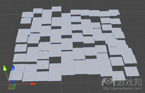
现在运行代码,你会看到如下图所示的模型:
现在看它的基本布局,但mesh效果似乎不太好。我们把这些分散的平面组合成一个吧。为此,我们要先使邻近的quad共享顶点,而不是给每一个quad做4个顶点。事实上,我们只需给各个面做一个顶点。然后这个quad就可以使用这个点做出之前的行和列。新函数如下:
void BuildQuadForGrid(MeshBuilder meshBuilder, Vector3 position, Vector2 uv,
bool buildTriangles, int vertsPerRow)
{
meshBuilder.Vertices.Add(position);
meshBuilder.UVs.Add(uv);if (buildTriangles)
{
int baseIndex = meshBuilder.Vertices.Count – 1;int index0 = baseIndex;
int index1 = baseIndex – 1;
int index2 = baseIndex – vertsPerRow;
int index3 = baseIndex – vertsPerRow – 1;meshBuilder.AddTriangle(index0, index2, index1);
meshBuilder.AddTriangle(index2, index3, index1);
}
}
你会发现这个和之前的版本有许多不同之处。我们使用的位置offset作为顶点位置,因为这是可以增加的。另外,UV座标从外部代码通过,以避免和模型中的所有顶点相同。你会发现没有确定法线——我们之后再做这个。
最有趣的是三角形。它们并不是每次做的。这是因为各个quad 使用之前的行和列的顶点。如果这是任何行或列的第一个顶点,那么就没有之前的顶点可以做quad 了。
index也不同。我们从最后一个顶点index出发,并反向。前面的index是来自前一列的顶点。前一行的index必须减去这一行的index值。
以我的经验,计算三角形index是程序模型生成中最麻烦的部分,因为每次mesh算法改变,就要返回修改index。
我们再看一下调用这个函数的代码:
for (int i = 0; i <= m_SegmentCount; i++)
{
float z = m_Length * i;
float v = (1.0f / m_SegmentCount) * i;for (int j = 0; j <= m_SegmentCount; j++)
{
float x = m_Width * j;
float u = (1.0f / m_SegmentCount) * j;Vector3 offset = new Vector3(x, Random.Range(0.0f, m_Height), z);
Vector2 uv = new Vector2(u, v);
bool buildTriangles = i > 0 && j > 0;BuildQuadForGrid(meshBuilder, offset, uv, buildTriangles, m_StepCount + 1);
}
}
注意,我们是在根据位置offset计算UV。另外还要注意i和j要大于0。这就是我们停止每行或列的第一个顶点再做三角形的办法。
还有一个小小的不同。这个i和j循环的结束条件是“ <=”而不是“<”。因为第一个顶点不生成三角形,我们的地面平面在各个方向上现在还是比较小。作为弥补,我们让循环再进行一次。
最后,还记得那些我们没有计算的法线吗?在模型中,各个顶点的法线取决于与周围顶点有关的顶点位置。因为我们在各个顶点位置都有一些随机性,所以直到所有顶点都生成后才能计算法线。
事实上,我们可以作弊。Unity提供了一种计算法线的函数。
Mesh mesh = meshBuilder.CreateMesh();
mesh.RecalculateNormals();
注意那个Mesh.RecalculateNormals()并不总是最好的解决方案,可能产生奇怪的结果,特别是如果mesh有缝合处的话。这个我们之后再说。但对于我们现在这个平面,它是够用了。
盒子
盒子并不比quad来得复杂。它其实只是6个quad。
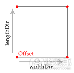
做一个盒子,我们要使用BuildQuad函数,以决定quad的面向。
void BuildQuad(MeshBuilder meshBuilder, Vector3 offset,
Vector3 widthDir, Vector3 lengthDir)
{
Vector3 normal = Vector3.Cross(lengthDir, widthDir).normalized;meshBuilder.Vertices.Add(offset);
meshBuilder.UVs.Add(new Vector2(0.0f, 0.0f));
meshBuilder.Normals.Add(normal);meshBuilder.Vertices.Add(offset + lengthDir);
meshBuilder.UVs.Add(new Vector2(0.0f, 1.0f));
meshBuilder.Normals.Add(normal);meshBuilder.Vertices.Add(offset + lengthDir + widthDir);
meshBuilder.UVs.Add(new Vector2(1.0f, 1.0f));
meshBuilder.Normals.Add(normal);meshBuilder.Vertices.Add(offset + widthDir);
meshBuilder.UVs.Add(new Vector2(1.0f, 0.0f));
meshBuilder.Normals.Add(normal);int baseIndex = meshBuilder.Vertices.Count – 4;
meshBuilder.AddTriangle(baseIndex, baseIndex + 1, baseIndex + 2);
meshBuilder.AddTriangle(baseIndex, baseIndex + 2, baseIndex + 3);
}
这看起来非常像我们之前使用的BuildQuad(),除了这里我们使用方向向量并添加到offse中,而不是直接把值插到X和Y位置。
这里,法线也可以轻易地计算了。只是两个方向的向量积。
注:或者,你可以写一个直接取四个角的位置的函数BuildQuad(),然后使用那些值。对于非常复杂的mesh,那可能是必须的,但对于我们的这个mesh,方向代码更简单清楚。
现在调用新函数:
MeshBuilder meshBuilder = new MeshBuilder();
Vector3 upDir = Vector3.up * m_Height;
Vector3 rightDir = Vector3.right * m_Width;
Vector3 forwardDir = Vector3.forward * m_Length;Vector3 nearCorner = Vector3.zero;
Vector3 farCorner = upDir + rightDir + forwardDir;BuildQuad(meshBuilder, nearCorner, forwardDir, rightDir);
BuildQuad(meshBuilder, nearCorner, rightDir, upDir);
BuildQuad(meshBuilder, nearCorner, upDir, forwardDir);BuildQuad(meshBuilder, farCorner, -rightDir, -forwardDir);
BuildQuad(meshBuilder, farCorner, -upDir, -rightDir);
BuildQuad(meshBuilder, farCorner, -forwardDir, -upDir);Mesh mesh = meshBuilder.CreateMesh();
这里,所有平面都来源于两个盒子中相对的角。注意近处的角是源头,意味着mesh将以此为轴点。把farCorner值除以2,nearCorner取其结果的负值。
Vector3 farCorner = (upDir + rightDir + forwardDir) / 2;
Vector3 nearCorner = -farCorner;
用心的读者会发现,第个quad都有4个顶点,所以整个盒子共有24个顶点。当然,如果只有8个,一角一个,使所有三角形共用顶点,那效率就更高了。是不是跟地面mesh一样?
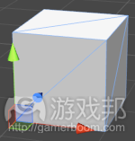
答案是否。这24个顶点我们都需要。这是因为即使顶点位置与各个角一样,法线(和UV)也是不一样的。如果法线共享,那么光照效果就会非常差。
通过分离各个quad的顶点,我们制作了一个沿着边的接合,使法线分到各个面。
注:也就是说,如果出于某些原因,你的mesh不使用法线或UV,那就重写代码共享顶点也是可以的——任何形状都行。如果你要渲染上百个物品,或者制作高模,这么做节约性能的效果是非常明显的。
好好做盒子吧。下一部分,我们将看看如何更好地利用基本形状,以做出更有意思的mesh。(本文为游戏邦/gamerboom.com编译,拒绝任何不保留版权的转载,如需转载请联系:游戏邦)
Modelling by numbers: Part One A
by Jayelinda Suridge
An introduction to procedural geometry
What and why?
Procedural geometry is geometry modelled in code. Instead of building 3D meshes by hand using art software such as Maya, 3DS Max or Blender, the mesh is built using programmed instructions.
This can be done at runtime (the mesh does not exist until the end-user runs the program), at edit time (using script or tool when the application is being developed), or inside a 3D art package (using a scripting language such as MEL or MaxScript).
Benefits of generating meshes procedurally include:
Variation: Meshes can be built with random variations, meaning you can avoid repeating geometry.
Scalability: Meshes can be generated with more or less detail depending on the end-user’s machine or preferences.
Control: Game/level designers with little knowledge of 3D modelling software can have more control over the appearance of a level.
Speed: Many variants of an object can be generated easily and quickly.
Who’s talking?
Some background on me: I’m a 3D-artist-turned-games-programmer-turned-solo-developer who thinks that taking an object and figuring out how to make it with a script is fun. Not an idea of fun that everyone shares, but that’s OK.
Here are some procedural examples from my own game projects:
The procedural parts of a level from Stranger’s Call (highest and lowest detail settings) (these are based on a randomly generated layout, so the same level never appears twice).
Plants from Ludus silva (these are created/edited in-game by the player).
I’ve had a few people look at images like these and want to know how it’s done. Well, it’s done by taking some basic shapes and then adding complications to them. Most of the procedural stuff I do can be reduced to two basic shapes: The plane and the cylinder.
So we’re going to learn how to make those.
Prerequisites/Assumed knowledge
For all examples, I’ll be using C# and Unity. All the important concepts should be transferable to the language/engine of your choice.
The ability to understand basic C# is going to be necessary, and some knowledge of 3D geometry will be helpful.
A handy quiz for those who are uncertain:
Do you know what classes, functions, arrays and for loops are?
If I write them in C# will you recognise them?
Do you understand what a 3D vector is? (Vector3 struct in Unity)
Do you know how to get the direction from one point to another?
How did you do? Passed? Excellent. Read On.
Didn’t do so well? You might want to check out the official Unity scripting tutorials, or Google “Basic C# tutorial” and look at any of the umpteen million results (C# Station is a decent one).
Preface – What’s a mesh?
Most people with a 3D art background or at least a basic knowledge of 3D art will be able to skip this preface. For anyone with little experience using 3D assets, here is a brief explanation of what such an asset involves.
What we will be constructing in the following tutorial is known as a polygon mesh. It can be defined as a series of points (vertices) in 3D space, as well as a series of triangles, where each triangle forms the surface between 3 vertices. Triangles may or may not share vertices.
Two 3D meshes. Lit (left) and wireframe, showing the triangle structure (right).
Triangles Vs. polygons
There’s a little bit of common terminology that should be clarified before we go much further. You’ve probably heard terms like “poly-count” or “high-poly”/”low-poly” before. In these cases, “polygons” usually refer to triangles, but it’s good to clarify with whoever is using these terms, if you can. Most 3D modelling software allows artists to work with polygons with any number of sides. A poly-count produced by that software may be counting those shapes instead. When it comes to render time, however, those shapes will have to be broken down into triangles because that’s what the graphics hardware understands. Triangles are all that Unity’s Mesh class understands, as well. So we will be working with triangles all the way.
We’ll be adding some additional data to our meshes, besides triangles and 3D positions. Like normals. These are the outward directions of the vertices. Normals are required in order to apply lighting to a mesh.
The other thing we’re going to be adding is UV coordinates (or just UVs). These are necessary for applying a texture to a mesh. A UV coordinate is a position in 2D (UV) space. The pixels of a texture at that coordinate are then applied to the mesh at that position. The UVs of a mesh are often referred to as its “unwrap”, because they can be thought of as the surface of the mesh being peeled away and flattened onto the texture space.
That’s the basic explanation of what a mesh is. Now let’s learn to make some.
Contents
This tutorial is quite long, so I’ll divide it into parts:
Part One A: The plane
The first of the basic building blocks: the plane and, by extension, the box.
Part One B: Making planes interesting
We’ll be looking at building two actual objects: a house and a fence.
Part Two A: The cylinder
The second of the two basic building blocks: the cylinder and, by extension, spheres and other round things.
Part Two B: Making cylinders interesting
More less-basic objects, a mushroom and a flower.
Part One A: The plane
Unity assets – Unity package file containing scripts and scenes for this tutorial (parts 1A and 1B).
Source files – Just the source files, for those that don’t have Unity.
OK, let’s start with a quad
The simplest shape of them all. This is a basic flat plane, with 4 vertices and 2 triangles.
We’ll start with the components we’ll need. This mesh will have vertices, triangles, normals and UV coordinates. The only absolutely necessary parts are the vertices and triangles. If your mesh is not going to be lit in the scene, you don’t need normals. If you’re not going to be applying a texture to the material, you don’t need UVs.
Vector3[] vertices = new Vector3[4];
Vector3[] normals = new Vector3[4];
Vector2[] uv = new Vector2[4];
Now we assign some values to our vertices. This code assumes two previously defined variables: m_Width and m_Length, which are, as you might expect, the width and length of our quad.
This mesh is built in the XZ plane, with the normal pointing straight up the Y axis (good for a ground plane, which we’ll be looking at later). You can change this around as you like, eg. using the XY, pointing down the Z axis (useful for billboards).
Position values all vary from 0.0f to the length/width, which will leave [0.0, 0.0] at the corner of the mesh. The origin of a mesh is its pivot point, so this mesh will pivot from that corner. If you want, you can offset the values by half the width and length to put the pivot at the centre.
vertices[0] = new Vector3(0.0f, 0.0f, 0.0f);
uv[0] = new Vector2(0.0f, 0.0f);
normals[0] = Vector3.up;
vertices[1] = new Vector3(0.0f, 0.0f, m_Length);
uv[1] = new Vector2(0.0f, 1.0f);
normals[1] = Vector3.up;
vertices[2] = new Vector3(m_Width, 0.0f, m_Length);
uv[2] = new Vector2(1.0f, 1.0f);
normals[2] = Vector3.up;
vertices[3] = new Vector3(m_Width, 0.0f, 0.0f);
uv[3] = new Vector2(1.0f, 0.0f);
normals[3] = Vector3.up;
Now we build our triangles. Each triangle is defined by three integers, each one being the index of the vertex at that corner. The order of vertices inside each triangle is called the winding order, and will either be clockwise or counterclockwise, depending on which side we are looking at the triangle from. Usually, the counterclockwise side (backface) will be culled when the mesh is rendered. We want to make sure the clockwise side faces in the same direction as our normal (ie. up).
int[] indices = new int[6]; //2 triangles, 3 indices each
indices[0] = 0;
indices[1] = 1;
indices[2] = 2;
indices[3] = 0;
indices[4] = 2;
indices[5] = 3;
Now lets put it all together. In Unity, this simply involves assigning all the arrays we just created to an instance of the Unity Mesh class. We call RecalculateBounds() at the very end to make the mesh recalculate its extents (it needs these for render culling).
Mesh mesh = new Mesh();
mesh.vertices = vertices;
mesh.normals = normals;
mesh.uv = uv;
mesh.triangles = indices;
mesh.RecalculateBounds();
Now we have a mesh that’s done and good to go. In our Unity scene, we’ve attached this script to a GameObject containing mesh filter and mesh renderer components. The following code looks for the mesh filter and assigns the mesh we just made to it. The mesh now exists as part of an object in our scene.
MeshFilter filter = GetComponent();
if (filter != null)
{
filter.sharedMesh = mesh;
}
You have now made your first procedural mesh.
While the basics sink in, let’s back up and do a little planning ahead
OK, let’s assume we’re going to be doing a fair bit of this procedural stuff for here on in. Something that get tedious is writing the same mesh initialisation code (the bit at the end) over and over again, but not as tedious as the errors that happen because you’ve slightly miscalculated the number of vertices/triangles you’re going to need at the beginning. Time to wrap it all up in class of its own.
using UnityEngine;
using System.Collections;
using System.Collections.Generic;
public class MeshBuilder
{
private List m_Vertices = new List();
public List Vertices { get { return m_Vertices; } }
private List m_Normals = new List();
public List Normals { get { return m_Normals; } }
private List m_UVs = new List();
public List UVs { get { return m_UVs; } }
private List m_Indices = new List();
public void AddTriangle(int index0, int index1, int index2)
{
m_Indices.Add(index0);
m_Indices.Add(index1);
m_Indices.Add(index2);
}
public Mesh CreateMesh()
{
Mesh mesh = new Mesh();
mesh.vertices = m_Vertices.ToArray();
mesh.triangles = m_Indices.ToArray();
//Normals are optional. Only use them if we have the correct amount:
if (m_Normals.Count == m_Vertices.Count)
mesh.normals = m_Normals.ToArray();
//UVs are optional. Only use them if we have the correct amount:
if (m_UVs.Count == m_Vertices.Count)
mesh.uv = m_UVs.ToArray();
mesh.RecalculateBounds();
return mesh;
}
}
All the data you’ll need is now in one class that’s easy to pass between functions. Also, because we’re using generic lists instead of arrays, there’s no miscalculating the number of vertices or triangles required. Plus it makes it easier to combine meshes: just generate them using the same MeshBuilder.
Note: This is a simplified version of the class I use in my own projects. There are things it doesn’t do, like tangents and vertex colours, or reserving space for very large meshes, or altering existing instances of the Mesh class.
Now, using this class, our quad generation code looks like this:
MeshBuilder meshBuilder = new MeshBuilder();
//Set up the vertices and triangles:
meshBuilder.Vertices.Add(new Vector3(0.0f, 0.0f, 0.0f));
meshBuilder.UVs.Add(new Vector2(0.0f, 0.0f));
meshBuilder.Normals.Add(Vector3.up);
meshBuilder.Vertices.Add(new Vector3(0.0f, 0.0f, m_Length));
meshBuilder.UVs.Add(new Vector2(0.0f, 1.0f));
meshBuilder.Normals.Add(Vector3.up);
meshBuilder.Vertices.Add(new Vector3(m_Width, 0.0f, m_Length));
meshBuilder.UVs.Add(new Vector2(1.0f, 1.0f));
meshBuilder.Normals.Add(Vector3.up);
meshBuilder.Vertices.Add(new Vector3(m_Width, 0.0f, 0.0f));
meshBuilder.UVs.Add(new Vector2(1.0f, 0.0f));
meshBuilder.Normals.Add(Vector3.up);
meshBuilder.AddTriangle(0, 1, 2);
meshBuilder.AddTriangle(0, 2, 3);
//Create the mesh:
MeshFilter filter = GetComponent();
if (filter != null)
{
filter.sharedMesh = meshBuilder.CreateMesh();
}
Let’s get fancy – terrain
A terrain for your level. Or, really, just a bumpy plane.
Note: The “bumpiness” in this terrain is done by assigning a random height to each vertex. It’s done this way because it makes the code nice and simple, not because it makes a good looking terrain. If you’re serious about building a terrain mesh, you might try using a heightmap, or perlin noise, or looking into algorithms such as diamond-square.
This terrain can be thought of as a series of quads arranged in a grid. As a first step, we’re going to do exactly that. First, we define a function that builds a quad exactly like we did above. Only this function will take as an argument a position offset, which gets added to the vertex positions.
void BuildQuad(MeshBuilder meshBuilder, Vector3 offset)
{
meshBuilder.Vertices.Add(new Vector3(0.0f, 0.0f, 0.0f) + offset);
meshBuilder.UVs.Add(new Vector2(0.0f, 0.0f));
meshBuilder.Normals.Add(Vector3.up);
meshBuilder.Vertices.Add(new Vector3(0.0f, 0.0f, m_Length) + offset);
meshBuilder.UVs.Add(new Vector2(0.0f, 1.0f));
meshBuilder.Normals.Add(Vector3.up);
meshBuilder.Vertices.Add(new Vector3(m_Width, 0.0f, m_Length) + offset);
meshBuilder.UVs.Add(new Vector2(1.0f, 1.0f));
meshBuilder.Normals.Add(Vector3.up);
meshBuilder.Vertices.Add(new Vector3(m_Width, 0.0f, 0.0f) + offset);
meshBuilder.UVs.Add(new Vector2(1.0f, 0.0f));
meshBuilder.Normals.Add(Vector3.up);
int baseIndex = meshBuilder.Vertices.Count – 4;
meshBuilder.AddTriangle(baseIndex, baseIndex + 1, baseIndex + 2);
meshBuilder.AddTriangle(baseIndex, baseIndex + 2, baseIndex + 3);
}
Note also the vertex indices for the triangles. This time, we are adding an unknown number of quads to the MeshBuilder, instead of just one. Instead of index 0, we need to start from the beginning of the vertices we just added.
Now to call the function we just wrote. Pretty simple, just a pair of loops that call BuildQuad(), increasing the X and Z values of the offset each time:
MeshBuilder meshBuilder = new MeshBuilder();
for (int i = 0; i < m_SegmentCount; i++)
{
float z = m_Length * i;
for (int j = 0; j < m_SegmentCount; j++)
{
float x = m_Width * j;
Vector3 offset = new Vector3(x, Random.Range(0.0f, m_Height), z);
BuildQuad(meshBuilder, offset);
}
}
If you run this code, you’ll end up with a mesh that looks something like this:
We can see the basic layout now, but the mesh isn’t much good like this. Let’s join the whole thing up into one. To do this, we need adjacent quads to share their vertices instead of making four new ones each. In fact, we only need to create one vertex for each section. The quad can then use this, and the vertices from the previous row and column. The new function looks like this:
void BuildQuadForGrid(MeshBuilder meshBuilder, Vector3 position, Vector2 uv,
bool buildTriangles, int vertsPerRow)
{
meshBuilder.Vertices.Add(position);
meshBuilder.UVs.Add(uv);
if (buildTriangles)
{
int baseIndex = meshBuilder.Vertices.Count – 1;
int index0 = baseIndex;
int index1 = baseIndex – 1;
int index2 = baseIndex – vertsPerRow;
int index3 = baseIndex – vertsPerRow – 1;
meshBuilder.AddTriangle(index0, index2, index1);
meshBuilder.AddTriangle(index2, index3, index1);
}
}
You’ll notice many differences between this and the previous version. We’re using the position offset as the vertex position, since this will be incremented anyway. Also the UV coordinates are being passed in from the external code, to avoid them being the same for every vertex in the mesh. You will also notice that no normal is being defined – we’ll get to that later.
The most interesting bit is the triangles. They aren’t being built every time. This is because each quad uses vertices from the previous row and column. If this is the first vertex in any row or column, there will be no previous vertices to build a quad with.
The indices also differ. We start from the last vertex index and work backward from there. The previous index is the vertex from the previous column. Vertices from the previous row need to subtract the number of vertices in a row from the index.
In my experience, calculation of triangle indices is the pickiest part of procedural mesh generation. Always go and check your indices whenever mesh algorithms change.
Let’s revisit the code the calls this function:
for (int i = 0; i <= m_SegmentCount; i++)
{
float z = m_Length * i;
float v = (1.0f / m_SegmentCount) * i;
for (int j = 0; j <= m_SegmentCount; j++)
{
float x = m_Width * j;
float u = (1.0f / m_SegmentCount) * j;
Vector3 offset = new Vector3(x, Random.Range(0.0f, m_Height), z);
Vector2 uv = new Vector2(u, v);
bool buildTriangles = i > 0 && j > 0;
BuildQuadForGrid(meshBuilder, offset, uv, buildTriangles, m_StepCount + 1);
}
}
Notice we’re calculating UVs alongside the position offset. Also notice the check for i and j being greater than zero. This is how we stop the first vertex in each row or column from building triangles.
One other (and subtler) difference. The i and j loops now use <= instead of < in their end condition. Because the first vertices don’t generate triangles, our ground plane is now one segment smaller in each direction. We let the loops run one extra time to compensate.
Last but not least, remember those normals we didn’t calculate? The normal for each vertex in a mesh like this depends on the vertex position relative to the surrounding vertices. Because we have some randomness in each vertex position, normals can’t be calculated until after all the vertices have been generated.
Actually, we’re going to cheat. Unity provides a function to do the normals calculation for us.
Mesh mesh = meshBuilder.CreateMesh();
mesh.RecalculateNormals();
Note that Mesh.RecalculateNormals() isn’t always the best solution and can come up with odd-looking results, particularly if the mesh has seams. I’ll talk more about this later. For our noisy plane, however, it does the job just fine.
A familiar shape, the box
A box isn’t much more complicated than a quad. In fact, it’s just six quads.
To make one, though, we’ll need a BuildQuad() function that lets us tell it which direction we want the quad to face.
void BuildQuad(MeshBuilder meshBuilder, Vector3 offset,
Vector3 widthDir, Vector3 lengthDir)
{
Vector3 normal = Vector3.Cross(lengthDir, widthDir).normalized;
meshBuilder.Vertices.Add(offset);
meshBuilder.UVs.Add(new Vector2(0.0f, 0.0f));
meshBuilder.Normals.Add(normal);
meshBuilder.Vertices.Add(offset + lengthDir);
meshBuilder.UVs.Add(new Vector2(0.0f, 1.0f));
meshBuilder.Normals.Add(normal);
meshBuilder.Vertices.Add(offset + lengthDir + widthDir);
meshBuilder.UVs.Add(new Vector2(1.0f, 1.0f));
meshBuilder.Normals.Add(normal);
meshBuilder.Vertices.Add(offset + widthDir);
meshBuilder.UVs.Add(new Vector2(1.0f, 0.0f));
meshBuilder.Normals.Add(normal);
int baseIndex = meshBuilder.Vertices.Count – 4;
meshBuilder.AddTriangle(baseIndex, baseIndex + 1, baseIndex + 2);
meshBuilder.AddTriangle(baseIndex, baseIndex + 2, baseIndex + 3);
}
This looks very much like the BuildQuad() we used above, except here we use directional vectors and add them to the offset, instead of plugging values directly into the X and Z positions.
The normal can also be calculated easily here. It is merely the cross product of the two directions (make sure you normalise it).
Note: Alternatively, you could write a BuildQuad() function that directly takes the position of each of the four corners and uses those. For really complicated meshes, that may be necessary but, for our purposes, the directional code is much less messy.
Now to call our new function:
MeshBuilder meshBuilder = new MeshBuilder();
Vector3 upDir = Vector3.up * m_Height;
Vector3 rightDir = Vector3.right * m_Width;
Vector3 forwardDir = Vector3.forward * m_Length;
Vector3 nearCorner = Vector3.zero;
Vector3 farCorner = upDir + rightDir + forwardDir;
BuildQuad(meshBuilder, nearCorner, forwardDir, rightDir);
BuildQuad(meshBuilder, nearCorner, rightDir, upDir);
BuildQuad(meshBuilder, nearCorner, upDir, forwardDir);
BuildQuad(meshBuilder, farCorner, -rightDir, -forwardDir);
BuildQuad(meshBuilder, farCorner, -upDir, -rightDir);
BuildQuad(meshBuilder, farCorner, -forwardDir, -upDir);
Mesh mesh = meshBuilder.CreateMesh();
Here, all of the planes originate from two corners opposite each other in the box. Note that the near corner is the origin, meaning that the mesh will pivot from this corner. To pivot from the centre, simply divide farCorner by two and have nearCorner be the negative of that value:
Vector3 farCorner = (upDir + rightDir + forwardDir) / 2;
Vector3 nearCorner = -farCorner;
Observant readers will have noticed that every quad has its own 4 vertices, leaving the entire box with 24 vertices in total. Surely it’s more efficient to just have 8, one at each corner, and get all the triangles to share them, the same as the ground mesh?
Actually, the answer is no. We need all 24 of those vertices. This is because even though the vertex positions are the same at each corner, the normals (and the UVs, for that matter) are not. If the normals were shared, we’d get very bad looking lighting indeed:
By separating the vertices for each quad, we create a seam along the edges, allowing separate normals on each side:
Note: That said, if for some reason your mesh is using neither normals or UVs, feel free to rewrite the code to share the vertices – this goes for any shape. The performance saving is only likely to be noticeable if you’re rendering hundreds of the things, or are making very high-poly meshes, but you know your project better than I do.
Have fun with your box. In the next part of this tutorial, we’ll look at ways to extend the basic shapes we’ve learned to make some more interesting meshes.(source:gamsutra)
上一篇:探讨游戏开发者最大的营销误区







 闽公网安备35020302001549号